Circuit agc vfo oscillator seekic improvement possible should simple system which use over signal processing diagram Simple_agc Circuit agc simple circuits seekic control ic gif varying output input nbs aeronautical constant receiver relatively handbook signals communication preferred
The circuit of a simple AGC | Download Scientific Diagram
Agc simple Tikz circuits Delayed automatic gain control
Agc limiter amplifier soft signals use
Agc rf circuit amplifier diagram system build diagramsSimple agc (linear diode detector) Agc circuit multisimSingle chip agc solutions for communications.
Am communication receiverA simple way to add agc to your communications receiver design Circuit agc seekic basic diagram icAgc illustrates stages.
Simple automatic gain control circuit diagram
Agc circuitVfo_agc_circuit The circuit of a simple agcGain control automatic agc understanding system analog output.
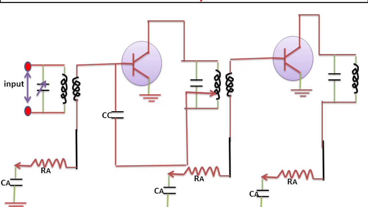
Agc circuit automatic receiver audio gain ssb 20m sch extremly important controll dk oz2cpu webxUse of an agc amplifier as a soft limiter of signals Agc circuit diagram communication receiver am delayed delay figureThe agc circuit. the diagram in 6(a) illustrates both stages of the.

Agc chip block diagram communications solutions single typical implemented discrete components fig solution
Agc fm circuit gain control automatic transmitter preamp mic electroschematics microphone circuits mosfetCircuit am agc receiver if diagram auxiliary communication typical stage figure Agc simple detector diode linearUnderstanding automatic gain control.
Agc circuit audio signals system seekic amplifierAc circuits – tikz.net Automatic gain controlNew agc circuit.

Agc delayed circuit neets rf action electricity detector gain automatic control radio frequency figure diode tpub
Homebrew 20m rig agcBuild a agc system for ca3028 rf amplifier circuit diagram Am communication receiverAgc way.
Bitx hacks: agc for the bitxThe circuit of a simple agc Agc_system_for_audio_signalsAgc bitx circuit audio here simple hacks volume control fits around.


AGC Circuit - Multisim Live

Single Chip AGC Solutions for Communications | 2012-05-15 | Microwave

AGC_SYSTEM_FOR_AUDIO_SIGNALS - Electrical_Equipment_Circuit - Circuit

The circuit of a simple AGC | Download Scientific Diagram

Delayed Automatic Gain Control

BITX Hacks: AGC for the BITX

Automatic Gain Control - AGC Circuit

The AGC circuit. The diagram in 6(a) illustrates both stages of the
